
2.4 Maximum Minimum Offset ( 3D )
The minimum offset in a 2D seismic survey is the distance between the source and the nearest receiver. In a 3D survey, this small offset is called: minimum-minimum offset.
However, in a 3D design, there is a more important parameter which is called the maximum-minimum offset or largest minimum offset ($X_{min}$).
The Geometry of the Box
In a 3D design, the Box is defined as the area between two adjacent source lines and two adjacent receiver lines. The diagonal of the box is the largest minimum offset ($X_{min}$).
This is the distance (in depth) to have one-single fold continuously. It should be less than 1.0 to 1.2 times depth of the shallowest horizon to be mapped.

Fig. 1 In a 3D design, the Box is defined as the area between two adjacent source lines and two adjacent receiver lines. The diagonal of the box is the largest minimum offset ($X_{min}$).
Shallow Reflector Sampling Criteria
It should be small enough to adequately sample shallow reflectors that might be used for datuming or isochroning purposes. A T-X schematic section along the $X_{min}$ of a Box reveals that the gap in the data shallower than $X_{min}$ is due to the mute pattern to be applied in processing.
The shallowest target should be sampled at least 4 times for a reliable interpretation (Fold = 4). This one is getting at $X_{sh}$ (X-shallow). The geometric rule of thumb dictates:
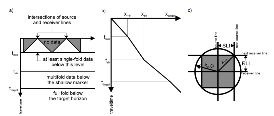
Fig. 2 (2a) shows a T-X schematic section along the $X_{min}$ of a Box. The gap in the data shallower than $X_{min}$ is due to the mute pattern on (2b) to be applied in processing. The shallowest target should be sampled at least 4 times for a reliable interpretation (Fold = 4). This one is getting at $X_{sh}$ (X-shallow). (2c) shows the rule of thumb layout: $X_{sh} = 2 X_{min}$.
Layout Spacing Constraints
This parameter and the required fold strongly define the distance between the source (SLI) and receiver line (RLI).
RLI should be chosen small enough to guarantee the necessary refraction measurements.